Local Area Network (LAN) Topologies
Star topology – In a star topology, devices are individually connected via a central networking device, i.e. a switch or hub. It is the most commonly found topology due to its reliability and scalability.
Information sent to a device in a star topology is sent via the central device to which it connects.
Disadvantages
- More expensive than any other topology.
- Though it has a much more scalable nature, the more the network scales, the more maintenance is required to keep the network functionable.
- As a result of more dependence on maintenance, troubleshooting faults are much harder.
- Still prone to failure, though reduced from other topologies.
- If central hardware that connects devices fails, these devices will no longer be able to send or receive data.
Bus topology – In a bus topology, the connection relies on a single connection known as a backbone cable. The structure is similar to that of a leaf off of a tree in the sense that devices stem from where the branches are on this cable.
Bus topologies are one of the easier and more cost-efficient topologies to set up because of their expenses, such as cabling or dedicated networking equipment used to connect these devices.
Disadvantages
- Because all data for each device travels along the same cable, it is very quickly prone to becoming slow and bottlenecked if devices are simultaneously requesting data.
- These bottlenecks also result in very difficult troubleshooting because it quickly becomes difficult to identify which device is experiencing issues with all the data travelling along the same route.
- Little redundancy in place in case of failures. There is a single point of failure along the backbone cable. If this cable were to break, devices can no longer receive or transmit data along the bus.
Ring Topology – In a ring topology, devices such as computers are connected directly to each other to form a loop, meaning that there is little cabling required and less dependence on dedicated hardware such as within a star topology.
A ring topology works by sending data across the loop until it reaches the destined device, using other devices along the loop to forward the data. Interestingly, a device will only send received data from another device in this topology if it does not have any to send itself. If the device happens to have data to send, it will send its own data first before sending data from another device.
Subnetting
While you know where to send information in real life to the correct department, networks need to know as well. Network administrators use subnetting to categorize and assign specific parts of a network to reflect this.
Subnetting is achieved by splitting up the number of hosts that can fit within the network, represented by a number called a subnet mask.
An IP address is made up of four sections called octets. The same goes for a subnet mask which is also represented as a number of four bytes, ranging from 0 to 255.
Subnets use IP addresses in three different ways:
Identify the network address
Identify the host address
Identify the default gateway
Network Address – This address identifies the start of the actual network and is used to identify a network’s existence.
- For example, a device with the IP address of 192.168.1.100 will be on the network identified by 192.168.1.0
Host Address – An IP address here is used to identify a device on the subnet.
- For example, a device will have the network address of 192.168.1.1. The host address might be 192.168.1.100.
Default Gateway – The default gateway address is a special address assigned to a device on the network that is capable of sending information to another network.
- Any data that needs to go to a device that isn’t on the same network (i.e. isn’t on 192.168.1.0) will be sent to this device. These devices can use any host address but usually use either the first or last host address in a network (.1 or .254). The address might look like 192.168.1.254.
ARP Protocol
The ARP protocol or Address Resolution Protocol for short, is the technology that is responsible for allowing devices to identify themselves on a network.
Simply, the ARP protocol allows a device to associate its MAC address with an IP address on the network. Each device on a network will keep a log of the MAC addresses associated with other devices.
When devices wish to communicate with another, they will send a broadcast to the entire network searching for the specific device. Devices can use the ARP protocol to find the MAC address of a device for communication.
How It Works
Each device within a network has a ledger to store information on, which is called a cache. In the ARP protocol, this cache stores the identifiers of other devices on the network.
In order to map the MAC and IP addresses together, the ARP protocol sends two types of messages: ARP Request and ARP Reply.
When an ARP request is sent, a message is broadcasted to every other device found on a network by the device, asking whether or not the device’s MAC address matches the requested IP address. If the device does have the requested IP address, an ARP reply is returned to the initial device to acknowledge this. The initial device will now remember this and store it within its cache (an ARP entry).
The DHCP Protocol
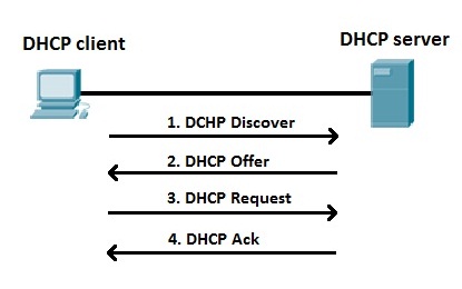
IP addresses can be assigned either manually, by entering them physically into a device, or automatically and most commonly by using a DHCP (Dynamic Host Configuration Protocol) server. When a device connects to a network, if it has not already been manually assigned an IP address, it sends out a request (DHCP Discover) to see if any DHCP servers are on the network. The DHCP server then replies back with an IP address the device could use (DHCP Offer). The device then sends a reply confirming it wants the offered IP Address (DHCP Request), and then lastly, the DHCP server sends a reply acknowledging this has been completed, and the device can start using the IP Address (DHCP ACK).